The KIDS survey
Intro: what is KIDS
- KIDS, the KIlo-Degree Survey, is a 1500 square degree public imaging survey in the Sloan colors (u',g',r',i',z') with patches in both the Northern and Southern skies. The survey will use the OmegaCAM instrument mounted on the VST (VLT Survey Telescope). It will start summer 2011.
- A parallel survey called VIKING (VISTA Kilo-degree INfrared Galaxy survey) is taking place on the VISTA telescope on Cerro Paranal since February 2010. It covers the 1500 square degree of the VST-KIDS survey in the 5 broadband filters Z,Y,J,H,Ks. Combined with KIDS, this will yield a unique 9-band optical-IR survey with depth approximately 2 mag deeper than Sloan and 1.4 mag deeper than UKIDSS-LAS.
The proposal to ESO
| Complete proposal text | (PDF) |
| ESOFORM template pt. 1 | (PDF) |
| ESOFORM template pt. 2 | (PDF) |
| ESOFORM template pt. 3 | (PDF) |
| Management plan v.2006/4/15 | (PDF) |
The time allocation
Here's what has been approved (in hours):| Period | u,d,0.85-1.1 | g,d,0.7-0.85 | r,d,< 0.7 | i,b,< 1.1 | i-wide,b,< 1.1 | calib,b,any |
| P77 | 60 | 60 | 119 | 143 | 51 | 43 |
| P78 | 60 | 60 | 119 | 143 | 51 | 43 |
| P79 | 60 | 60 | 119 | 143 | 51 | 21 |
| P80 | 60 | 60 | 119 | 143 | 51 | 21 |
| P81 | 60 | 60 | 119 | 143 | 51 | 21 |
| P82 | 60 | 60 | 119 | 143 | 51 | 21 |
| P83 | 60 | 60 | 119 | 143 | 51 | |
| P84 | 60 | 60 | 119 | 143 | 51 | |
| TOT | 480 | 480 | 952 | 1144 | 408 | 170 |
| GRAND TOT | 3634 | |||||
| P85 | 120 | |||||
| P86 | 120 | |||||
| P87 | 120 | |||||
| P88 | 120 | |||||
| TOT REPEAT | 480 | |||||
| GRAND TOT INC REPEAT | 4114 |
The fields
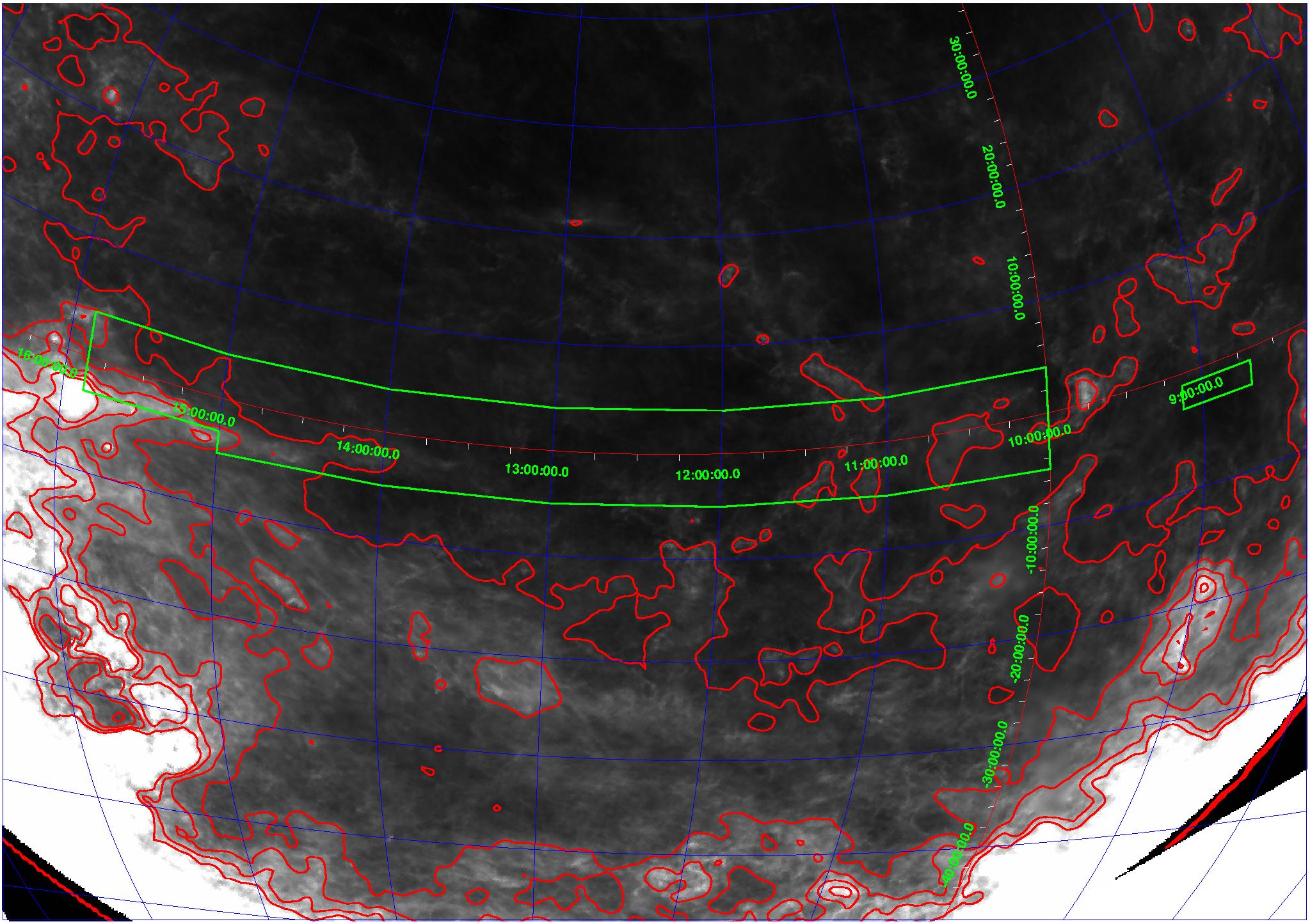
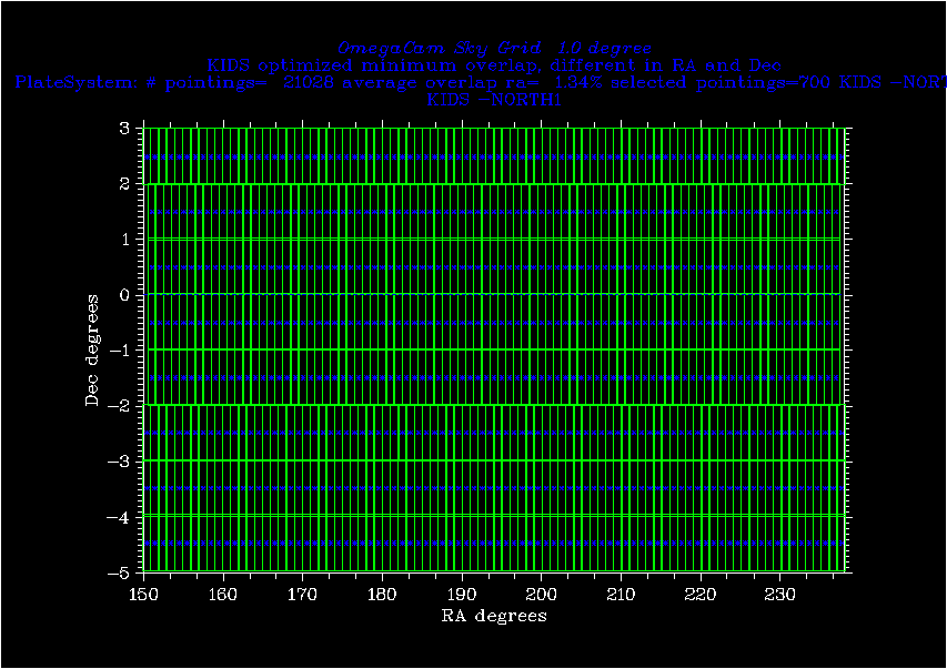
KIDS will target two patches, KIDS-N and KIDS-S. The total area is 1500 sq.deg.KIDS-N runs along the equator in the NGC, from RA 10:00 to 15:52 (150 to 238 deg), and between declination -5 and +3 (with the exception of RA> 15, dec< -3). In addition it includes the area RA 8:40 to 9:08, dec -3 to -1.
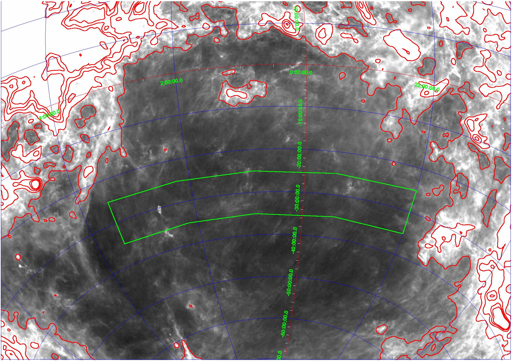
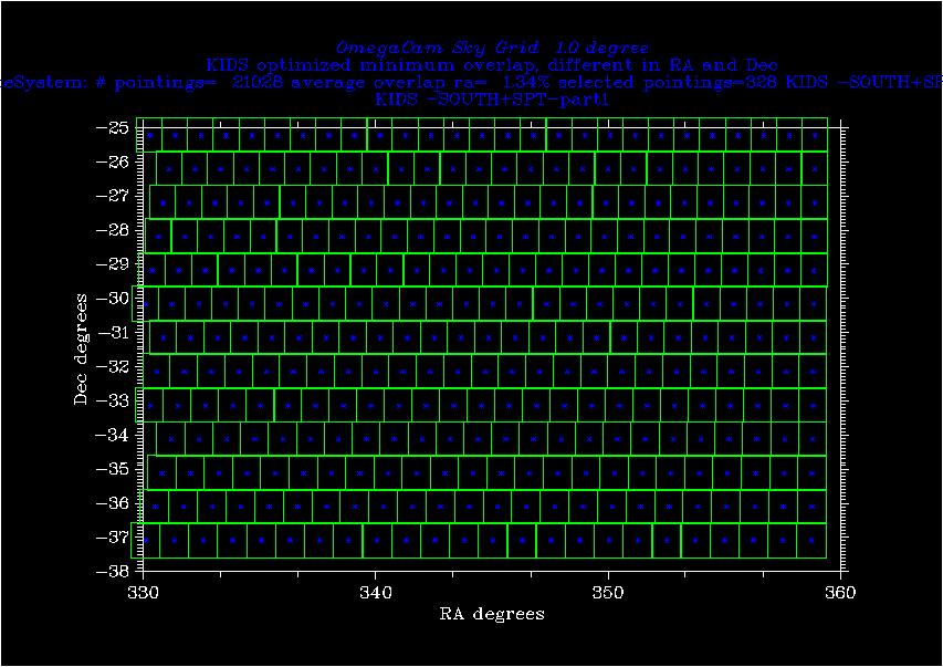
KIDS-S is a single rectangular patch around the SGP, between RA=22:00 and 3:30, and dec -35 to -25.
The location of the fields, plotted on top of the Schlegel,
Finkbeiner, & Davis 1998, ApJ, 500, 525 reddening maps, is shown
below. The areas are outlined in green; B-V extinction is contoured at
intervals of 0.05.
Click on the images for a larger version.
| KIDS-N: |
 |
| KIDS-S: |
 |
Order in which fields are to be observed
To increase the science return from the survey before it is completed, we have considered the best order in which to build up the survey. Relevant considerations are- a desire to get a useful angular power spectrum on large scales
- a wish to maximize coverage of the GAMA AAO spectroscopic survey patch contained in KIDS-N
- not compromise schedulability
- build in some overlaps of adjacent fields to allow calibration to be checked and improved
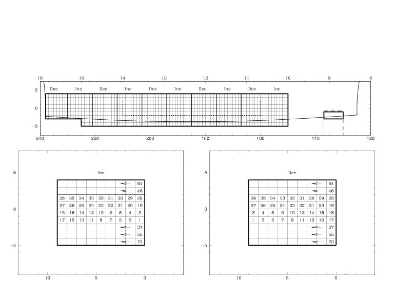
The KIDS-N patch is divided into square blocks, 9x9 degrees. A half-hour integration, plus 25% overheads, takes about 38 minutes, and in this time the sky rotates 9 degrees on the equator. So on a good night one field can be observed from each block in r, or two fields in g (or u), etc.
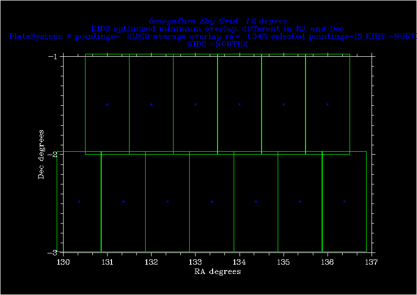
The blocks come in two varieties, 'inc' and 'dec' (increasing and decreasing RA coverage). They alternate along the KIDS patch.
Within a block the sequence of observation is as shown in the lower panels of the figures. The first two declination strips are observed in opposite directions in the two blocks, so that where the blocks meet contiguous areas build up rather quickly. After about 1/4 of the patch is observed we will have a complete 2 degree-wide strip. From this point on, the remaining strips can be built up in order of increasing RA, and the distinction between Inc and Dec is no longer important.
The first fours strips to be completed are those between declinations -2 and +2, where the spectroscopic AAO survey will take place.
In the KIDS-S patch (declination -30) the sky rotates a factor 0.87 more slowly, so here the natural width of a block in RA is 8, not 9 degrees.
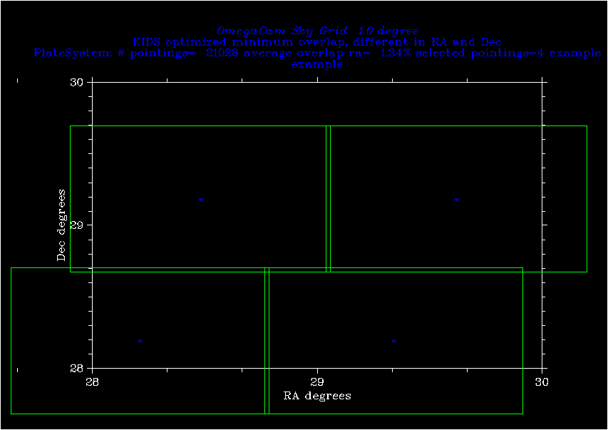
Tiling strategy
To avoid holes in the KIDS images, observations will be dithered with offsets sufficiently large to bridge the inter-CCD gaps of OmegaCAM. We will use 5 dithered exposures per field, which results in an exposure map that looks like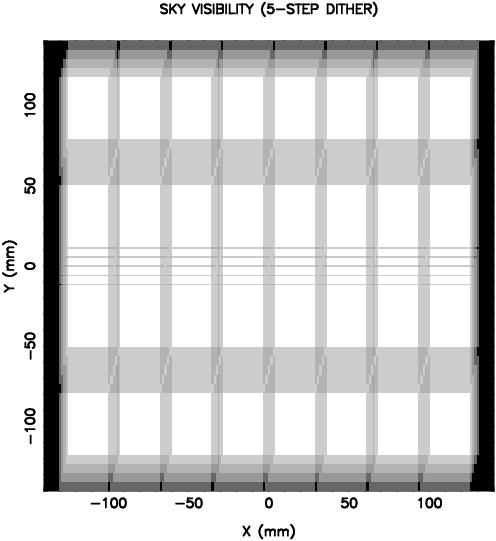
where white indicates the area covered in all 5 exposures, and progressively darker shades indicate lower and lower total exposure time.
At the edges of the fields, the exposure level decreases from 5 to 0, in a staircase pattern with step width equal to the dither steps (25 arcsec in X, 85 arcsec in Y).
The adjacent fields should mesh with each other in a nice way. Two
possibilities are illustrated below (click on figure for postscript
version):
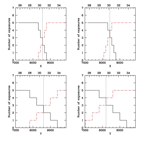 | ||||
| These panels show the exposure levels at the edges of two adjacent dithered images. The top panels show the exposure versus X, the lower panels versus Y (which has bigger steps). The horizontal axes are labelled in pixels (below) and arcminutes (above), and the center of the field is at (0,0). | ||||
| ||||
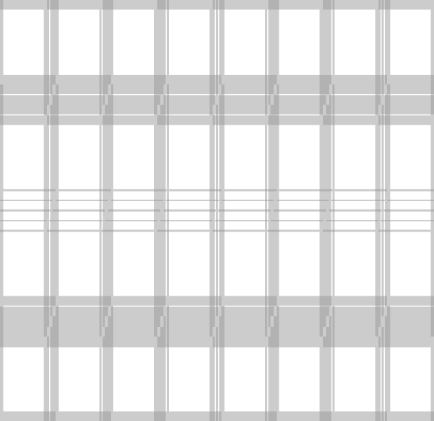
| Because of the redundancy and operational simplicity, option B is preferred. The resulting exposure pattern from a 2x2 set of fields is then as illustrated below. The darkest shade of grey represents 3/5 of the total exposure time. The grey horizontal and vertical strips marked with a + are the overlap regions where 4 exposures from one field overlap with three exposures from the adjacent one. | ||||
|
Further notes on KIDS Tiling and PlateSystem (Edwin Valentijn 8 June 2006)
Case B has a minimum overlap between adjacent fields. In itself this is not a problem, as the OmegaCAM calibration plan forsees for each field an independent photometric and astrometric calibration. However, some overlap is desired as an extra cross check on calibrations. Case B provides a few 100 pixels overlap with 1-3 dithers; and that is tight but just enough.
Here, we explore the possibility to adopt this scenario for a whole sky PlateSystem. ( see Tiling the Sky for OmegaCAM)
defs:
A field of fieldsize_ra* fieldsize_dec has a fieldcenter.
A 5 point dither points with respect to this fieldcenter has 2 times ++ and 2 times -- in steps ditherstep_dec and ditherstep_ra.
In fact for a 5 point dither the transitions at the edges of the fields will have number of frames
...... 5 5 6 7 7 7 7 6 5 5 ......... per ditherstep.
The central two 7 dither strips are composed of 3+ 4 and 4 +3 dithers of the two fieldcenters.
Thus these two strips have a minimum of 3 dithers per fieldcenter, which is what we define the overlap.
This means that without ditherstepping single fields overlap 2 dithersteps.
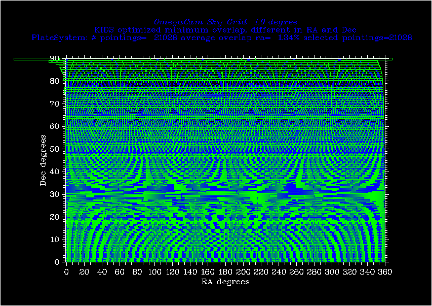
When designing a grid for a whole hemisphere this condition is kept as a strict minimum.
In practice, several effects cause a larger overlap than this minimum:
- in RA and DEC: putting an integer number of fields in
a RA strip, and on the meridian
- in RA: the cos (delta_dec) term over the 1 degree fieldsize_dec, which is larger than 200 px at dec <-45 at the top of an image compared to the bottom..
- in RA and DEC:
when ADC is in, the scale at the focal plane changes from 0.2134 to
0.2149 arcsec/pixel, enlarging the fieldsize_ra from 1.01270 to
1.01982 degrees, and the fieldsize_dec from 1.02451 to
1.02738 degrees, which implies an extra overlap of 112 px in both
directions.
- In Dec: differential atmospheric refraction enlarges fieldsize_dec
Case B also has the property that the average separation between fields in degrees is larger in Dec than in RA direction because of the large horizontal gaps between the CCDs ( 100 px in Ra= ditherstep_RA, 374 px in Dec= ditherstep_Dec).
For the two-lens corrector:
fieldsize_ra = 1.01270 degree
fieldsize_dec= 1.02451 degree
With these setttings PlateSystem instantiates a Grid::
requested overlap dec= 4 %
fieldsize dec = 1.02451 degrees, fieldsizera= 1.0127 degrees
achieved distance fieldcenters in dec: 0.989010989011 degrees
achieved overlap in dec: 3.58934444444 %
Version for parents of KIDS
The following table lists some properties for each of the dec strips:
sequence Dec number overlap-ra
[degrees] [min%] min[px] +top[px]
1 0.50 360 1.3 203 2
2 1.49 360 1.3 206 7
3 2.48 359 1.0 168 12
4 3.47 359 1.1 180 17
5 4.46 359 1.2 197 22
6 5.45 358 1.1 173 27
7 6.43 358 1.2 200 32
8 7.42 357 1.2 186 37
9 8.41 356 1.1 177 42
10 9.40 355 1.1 172 47
11 10.39 354 1.1 173 52
12 11.38 353 1.1 178 56
13 12.37 352 1.2 188 61
14 13.36 351 1.3 204 66
15 14.35 349 1.1 177 71
16 15.34 348 1.3 202 76
17 16.32 346 1.2 186 80
18 17.31 344 1.1 173 85
19 18.30 343 1.3 213 90
20 19.29 341 1.3 211 95
21 20.28 339 1.3 213 99
22 21.27 336 1.1 173 104
23 22.26 334 1.2 185 108
24 23.25 332 1.3 202 113
25 24.24 329 1.1 175 117
26 25.23 327 1.3 202 122
27 26.21 324 1.2 184 126
28 27.20 321 1.1 171 131
29 28.19 319 1.3 213 135
30 29.18 316 1.3 210 139
31 30.17 313 1.3 212 144
32 31.16 309 1.0 166 148
33 32.15 306 1.1 177 152
34 33.14 303 1.2 193 156
35 34.13 300 1.3 214 161
36 35.12 296 1.2 186 165
37 36.10 293 1.4 217 169
38 37.09 289 1.2 198 173
39 38.08 285 1.1 184 176
40 39.07 281 1.1 174 180
41 40.06 277 1.1 169 184
42 41.05 273 1.1 168 188
43 42.04 269 1.1 172 192
44 43.03 265 1.1 182 195
45 44.02 261 1.2 196 199
46 45.01 257 1.3 216 202
47 45.99 252 1.1 177 206
48 46.98 248 1.3 207 209
49 47.97 243 1.1 177 213
50 48.96 239 1.4 218 216
51 49.95 234 1.2 197 219
52 50.94 229 1.1 179 222
53 51.93 224 1.0 166 225
54 52.92 219 1.0 157 228
55 53.91 215 1.4 228 231
56 54.90 210 1.4 230 234
57 55.88 204 1.0 158 237
58 56.87 199 1.1 169 240
59 57.86 194 1.2 185 242
60 58.85 189 1.3 207 245
61 59.84 184 1.5 235 247
62 60.83 178 1.1 179 250
63 61.82 173 1.4 218 252
64 62.81 167 1.0 168 254
65 63.80 162 1.4 219 257
66 64.79 156 1.1 175 259
67 65.77 151 1.5 241 261
68 66.76 145 1.3 205 263
69 67.75 139 1.1 172 265
70 68.74 134 1.6 261 267
71 69.73 128 1.5 237 268
72 70.72 122 1.4 216 270
73 71.71 116 1.2 198 272
74 72.70 110 1.1 183 273
75 73.69 104 1.1 171 275
76 74.68 98 1.0 163 276
77 75.66 92 1.0 160 277
78 76.65 86 1.0 160 278
79 77.64 80 1.0 166 279
80 78.63 74 1.1 179 280
81 79.62 68 1.2 198 281
82 80.61 62 1.4 227 282
83 81.60 56 1.7 268 283
84 82.59 50 2.0 323 284
85 83.58 44 2.5 401 284
86 84.57 38 3.2 510 285
87 85.55 32 4.2 667 285
88 86.54 25 1.6 259 286
89 87.53 19 2.8 453 286
90 88.52 13 5.3 848 286
91 89.51 7 12.7 2030 286
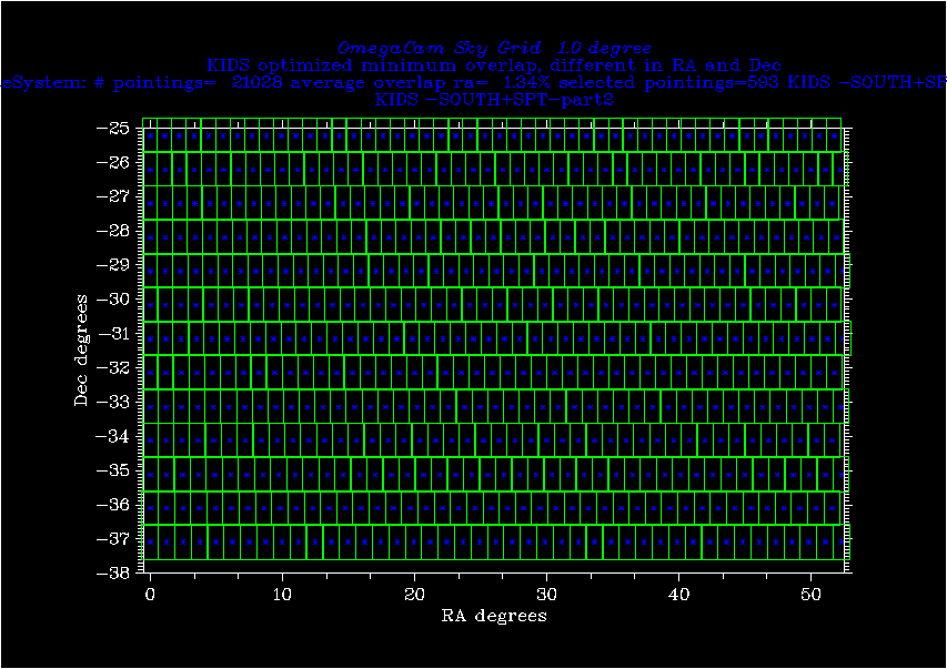
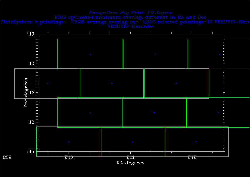
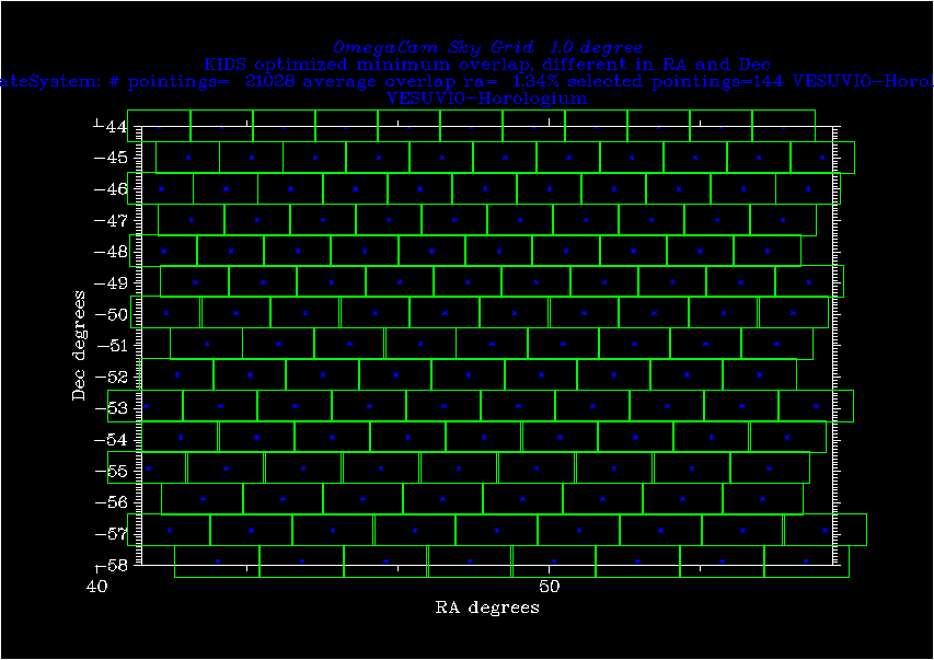
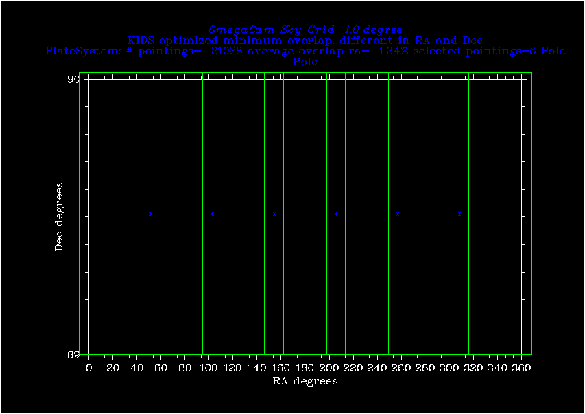
(rectangles depict the actual field size of OmegaCAM and overlap corresponds to at least two dithersteps)
I have included the anticipated survey areas for other surveys, like VESUVIO-Horlogium and VESUVIO-Hercules.
PlateSystem will really pay off when we can convince the various surveys to adopt the same tiling (common archive, data reductions-overlap handling!). Note that 2 hours/field propagates to 5*300 = 1500 field/year or 15000 fields/10 year.
So when only half of the anticipated lifetime of OmegaCAM will be devoetd to this kind of survey work 7500 fields can end up into the archive, which is about 36% of the southern Sky! So PlateSystem could become a power tool for our quest for larger area.
dd
dd
dd
dd
dd
ddd
ddd
dd