Preparing OmegaCAM Observations
We summarize on this page useful information to prepare a proposal for observing time with OmegaCAM.
The OmegaCAM User Manual - VST-MAN-OCM-23100-3110 - Version 1.2, K. Kuijken; 15.11.2004 (.pdf)
.ps Plan for tiling and pixelating the skyTechnical description of the instrument
OmegaCAM is a wide-field blue-optimized CCD camera, which will be the sole instrument on the 2.6m ESO-Paranal VLT Survey Telescope currently under construction. It has a 1x1 square degree field of view, tiled with 32 closely packed low-noise thinned E2V CCDs.Each image contains some 16400x16400 0.21 arcsec pixels. The design of VST and OmegaCAM ensures that image quality should be uniformly good all over the field.
An atmospheric dispersion corrector is available for work at high airmasses, but cannot be used in u band.
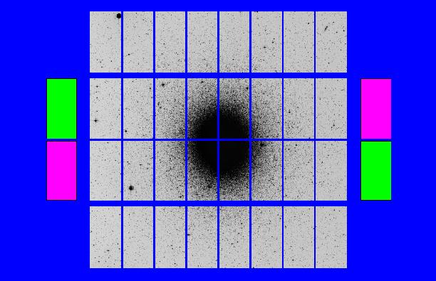
Cosmetic quality of the CCDs is good but not perfect, so some dithering is
required. The layout of the focal plane (including four auxiliary CCDs for
guiding and image quality measurement, and the globular cluster omega Cen for
your pleasure) is as follows:
OmegaCAM will have a high-throughput SDSS u'g'r'i'z' interference filter set, a Stromgren v filter, coloured-glass Johnson B and V filters, and a segmented 10-nm bandwidth Halpha interference filter mosaic with four quadrants at different central wavelengths (redshift 1100, 4200, 7300, 10400 for full width of 4900km/s). Some vignetting occurs on a central cross in the Johnson and Halpha filters.
The following figure shows the expected throughput of the VST/OmegaCAM system in the Sloan bands, and in the H-alpha filter.
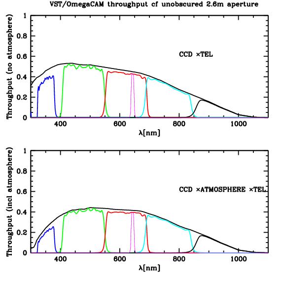
Further filters are under consideration, particularly a redshifted version of the Halpha set (z=0.3, in a dark window of the 800-900nm wavelength region) and a
mosaic of four narrow-band filters centered around 375, 400, 450 and 503nm (bandwidth 10nm). Both this filter mosaic, and the Halpha mosaic, generate full-field narrow-band images in four bands, of identical exposure times, if they are used in a 4-exposure sequence with 90 degree rotations in between.
Geographical information on VST
| altitude | 2635.43 m | |
| latitude | -24 deg 37 min 33.117 sec (UT1) | |
| longitude | 70 deg 24 min 11.642 sec (UT1) |
General Observing Conditions and Data for Paranal
Observing modes
We distinguish the following observing modes: 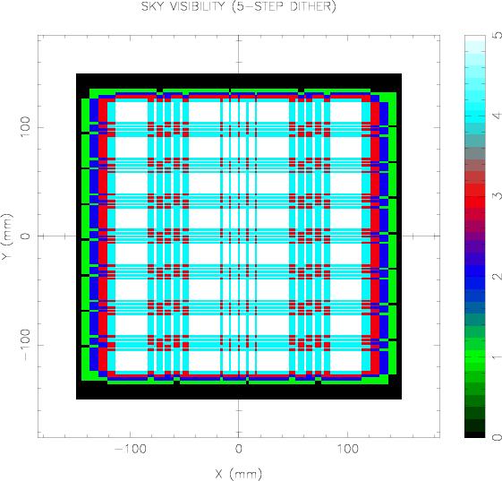 - Dither,
with large pointing offsets (nominally 5 pointings) of the order of 1-2
arcminutes optimised to the largest gaps between the CCDs (~400
pixels). This will lead to a full sky coverage but with a rather
complex weight map. At least 5 pointings are necessary to obtain a
sampling over the whole field that is uniform within a factor of 2 (see
colour-coding of image on the right, showing relative exposure times
after a fairly optimal 5-point dither).
- Dither,
with large pointing offsets (nominally 5 pointings) of the order of 1-2
arcminutes optimised to the largest gaps between the CCDs (~400
pixels). This will lead to a full sky coverage but with a rather
complex weight map. At least 5 pointings are necessary to obtain a
sampling over the whole field that is uniform within a factor of 2 (see
colour-coding of image on the right, showing relative exposure times
after a fairly optimal 5-point dither).
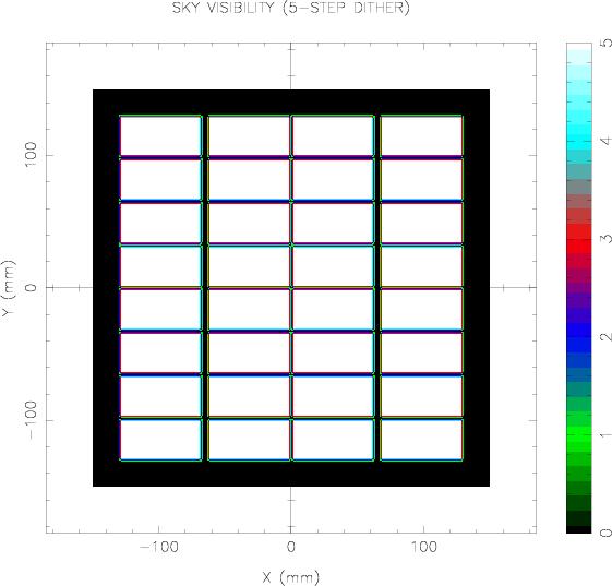 - Jitter,
with pointing offsets matching the smallest gaps between CCDs ~ 5
pixels, will lead to output images with incomplete sky-coverage but
with a very homogeneous sampling on the sky. The variation of noise
will be minimal over the whole field of view. It is the mode that
optimises homogeneity and will be used during observations for which
the wide CCD gaps are not critical
(see image on the right).
- Jitter,
with pointing offsets matching the smallest gaps between CCDs ~ 5
pixels, will lead to output images with incomplete sky-coverage but
with a very homogeneous sampling on the sky. The variation of noise
will be minimal over the whole field of view. It is the mode that
optimises homogeneity and will be used during observations for which
the wide CCD gaps are not critical
(see image on the right).
- SSO is the mode for observing Solar System Objects. It has non-sideral tracking and the auto guiding is switched off.
Observing strategies
An observing strategy employs one or a combination of the basic observing modes. It also defines a number of additional instructions for the scheduling of the observations. The observing strategy will be recorded in the FITS header of the observations. Optionally, the header information can be used in data reduction pipelines, in particular those operated by the Consortium when addressing the combination (e.g. stacking) of images.We discriminate among the following strategies:
-Standard which consists of a single observation (observation block);
-Deep which does deep integrations, possibly taken at selected atmospheric conditions over several nights;
-Freq which frequently visits (monitors) the same field on timescales ranging from minutes to months and has overriding priority on the telescope schedule;
-Mosaic maps area of the sky larger than 1 square degree, which is essentially an item for the scheduling, as the pipeline has to produce uniform quality data anyway. The combination of various field centers into one image is not considered a standard pipeline task.
OmegaCAM Exposure Time Estimator
There is currently no Exposure Time Estimator for OmegaCAM but one can use the following table as a guide. These numbers assume dark skies, and were computed with the proper filter profiles of OmegaCAM.10-sigma AB magnitudes (point source, dark time, 3 arcsec aperture); Halpha in erg/cm2/s
| Integration time | u' | g' | r' | i' | z' | B | V | Halpha |
|---|---|---|---|---|---|---|---|---|
| 100 s | 22.4 | 23.1 | 22.6 | 22.0 | 20.8 | |
|
1.2E-15 |
| 1000 s | 23.9 | 24.5 | 23.9 | 23.3 | 22.1 | |
|
2.8E-16 |
| 10000 s | 25.2 | 25.7 | 25.1 | 24.6 | 23.3 | |
|
8.4E-17 |
Oke AB mag = -2.5 log10(fnu) - 48.60, where fnu is in erg/s/cm^2/Hz
Oke AB mag = 23.9 - 2.5 log10(S/microJy)
To convert an Oke AB mag to a Vega (Johnson) magnitude, add approximately -0.8 (U), 0.2 (B), 0.0 (V), -0.1 (R), -0.3 (I)
10-sigma AB magnitudes (point source, grey time, 3 arcsec aperture); Halpha in erg/cm2/s
| Integration time | u' | g' | r' | i' | z' | B | V | Halpha |
|---|---|---|---|---|---|---|---|---|
| 100 s | 21.5 | 22.7 | 22.4 | 22.0 | 20.7 | |
|
|
| 1000 s | 22.9 | 24.0 | 23.7 | 23.2 | 22.0 | |
|
|
| 10000 s | 24.1 | 25.3 | 25.0 | 24.5 | 23.2 | |
|
|
10-sigma AB magnitudes (point source, dark time, 2 arcsec aperture); Halpha in erg/cm2/s
| Integration time | u' | g' | r' | i' | z' | B | V | Halpha |
|---|---|---|---|---|---|---|---|---|
| 100 s | 22.8 | 23.6 | 23.0 | 22.5 | 21.2 | |
|
|
| 1000 s | 24.3 | 24.9 | 24.3 | 23.8 | 22.5 | |
|
|
| 10000 s | 25.6 | 26.2 | 25.5 | 25.0 | 23.8 | |
|
|
10-sigma AB magnitudes (point source, grey time, 2 arcsec aperture); Halpha in erg/cm2/s
| Integration time | u' | g' | r' | i' | z' | B | V | Halpha |
|---|---|---|---|---|---|---|---|---|
| 100 s | 22.0 | 23.1 | 22.8 | 22.4 | 21.1 | |
|
|
| 1000 s | 23.3 | 24.4 | 24.1 | 23.7 | 22.4 | |
|
|
| 10000 s | 24.5 | 25.7 | 25.4 | 24.9 | 23.7 | |
|
|
A page of S/N vs exposure time plots,
including some of the other narrow-band filters,
is here.
Experience with the ESO/MPG 2.2m WFI is a useful guide, but note that
WFI and OmegaCAM filters are different.
Mode of operation
All data are taken in service mode by ESO. Some facility for quick-look data reduction in Chile may be possible, but otherwise it may take 2-3 weeks between the time the data are taken, and availability of the data.Data reduction
OmegaCAM data will be ingested into the Astro-WISE system, operated at the OmegaCEN data center in Groningen. This means that reduced images (astrometrically and photometrically calibrated, co-added) will be available, as well as source lists (based on SExtractor). The data can be worked on remotely, including extensive datamining facilities on the source lists and images, or exported.References
OmegaCAM: the 16k × 16k CCD Camera for the VLT Survey Telecope, in .pdf format, as published in ESO Messenger 110. .OmegaCAM: The 16k × 16k Survey Camera for the VLT Survey Telescope
Article by E. Deul, K. Kuijken and E. Valentijn, in ps or pdf format.
Click here for March 2003 PowerPoint Presentation