OmegaCAM ghosts
Konrad Kuijken, July 4 2002
Based on Harald's ZMAX calculations.
THREE-LENS CORRECTOR (TLC)
Two sets of ghosts are particulary important for this configuration.
 The first set is caused by internal reflections in the filter
sandwich. There are a series of them as there are many possible
combinations of 2 reflections (the filter sandwich has 4 surfaces,
with separations ca 5, ca 10 and ca 15 mm). These overlap the primary
image, and so obviously cannot be removed with any dithering
strategy. These effectively form part of the PSF.
The first set is caused by internal reflections in the filter
sandwich. There are a series of them as there are many possible
combinations of 2 reflections (the filter sandwich has 4 surfaces,
with separations ca 5, ca 10 and ca 15 mm). These overlap the primary
image, and so obviously cannot be removed with any dithering
strategy. These effectively form part of the PSF.
 In addition there is an offset ghost which is caused by a reflection
off the dewar window entrance, followed by a second reflection off the
filter exit surface.
In addition there is an offset ghost which is caused by a reflection
off the dewar window entrance, followed by a second reflection off the
filter exit surface.
The following cutouts show the locations of these main (most focussed)
ghosts at 5 field positions (0, 0.15, 0.30, 0.45 and 0.60 degrees from
the optical axis). The cross gives the primary image position, each
circle enscribes the rays for a ghost. Each panel shows a set
of concentric ghosts centered on the primary image: these are caused
by the internal filter reflections. The offset ghost is due to
reflections off the entrance surface of the dewar window.
The distance from a primary image to the center of the offset ghost
can be described by the formula
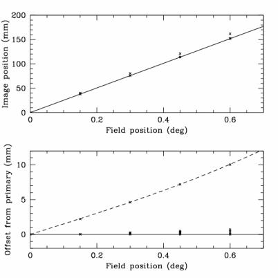
Delta_Rghost[mm] = 15 R[deg] + 5 R[deg]**3
where R is the location of the source in the field, in degrees. In
terms of R[mm], the location of the primary source in the focal plane,
the formula reads (1degree=253mm)
Delta_Rghost[mm] = 0.059 R[mm] + 3.1E-07 R[mm]**3
In the figure the solid line in the top diagram is the linear plate
scale of the primary images. The lower panel gives the location of the
ghosts with respect to the primary images; the dashed line is the
cubic fitting formula for the offset ghost location.
The size (radius) of the offset ghost is well-fitted by the formula
Rad[mm] = 0.82 + 2.6 R[deg]**2 = 0.82 + 4.1E-5 R[mm]**2
DITHERING STRATEGY TO DEAL WITH GHOSTS
It is possible to remove the offset ghosts by taking repeated dithered
exposures. The ghosts then fall at different locations on the focal
plane with respect to the primary images, and if the dither steps are
appropriately chosen then the ghost can be made
non-overlapping. 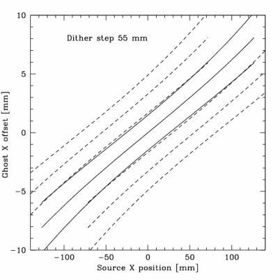 A ghostfree image can then be constructed by masking
the ghosts of bright stars before stacking the images.
A ghostfree image can then be constructed by masking
the ghosts of bright stars before stacking the images.
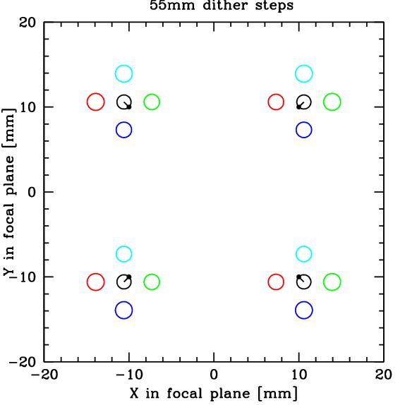
The minimum size dither step that is needed to ensure that no ghosts
overlap anywhere in the field is about 55mm, or 13 arcminutes, or 800
arcsec (see figure).
The figure shows the X-offset and width of a ghost for images on the X
axis (solid lines). The dashed lines show how these ghosts move if the
telescope is repointed so that all sources move 50 mm up or down in
X.
Smaller dithers than 55mm will give rise to overlaps in the outer
edges of the field. Dithers smaller than 27mm (6.4 arcmin, 400 arcsec)
give overlapping ghosts everywhere, even near the center of the field.
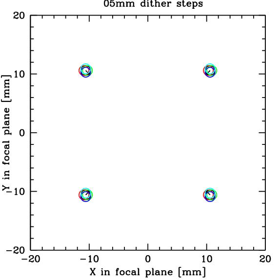
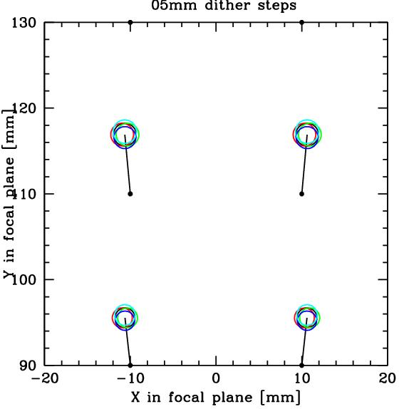
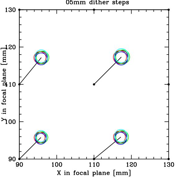
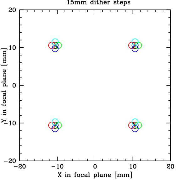
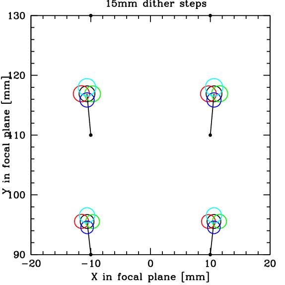
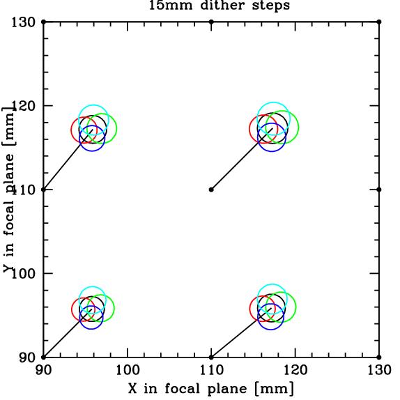
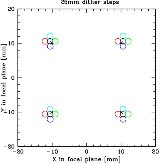
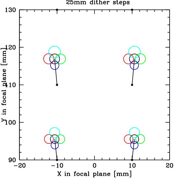
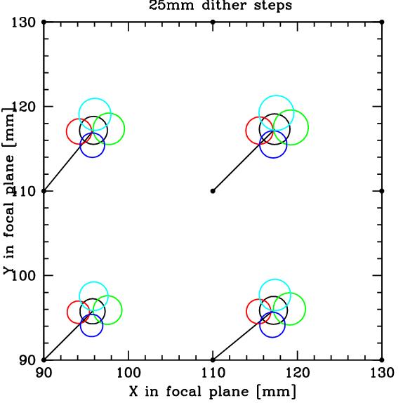
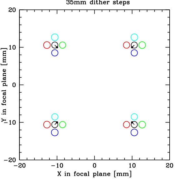
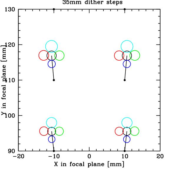
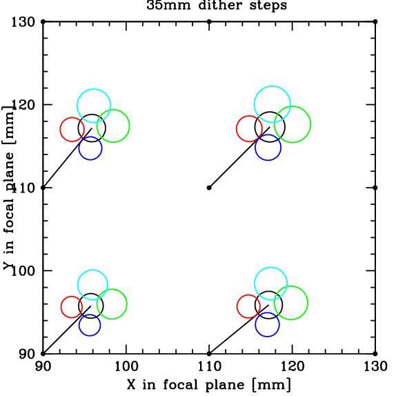
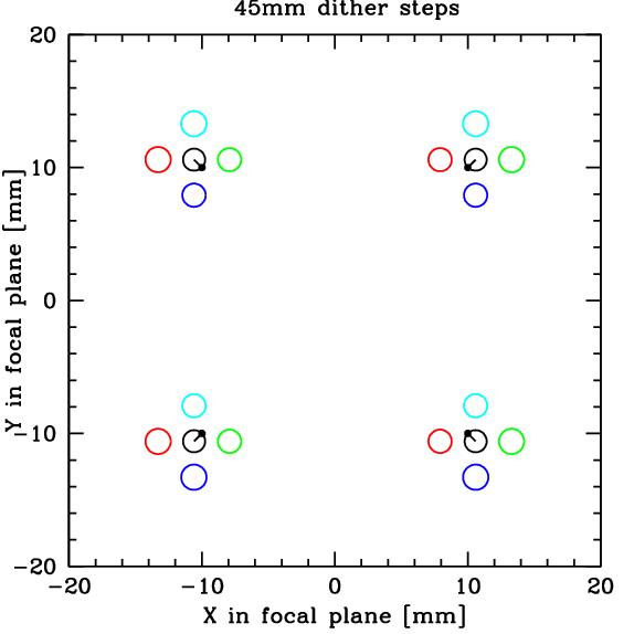
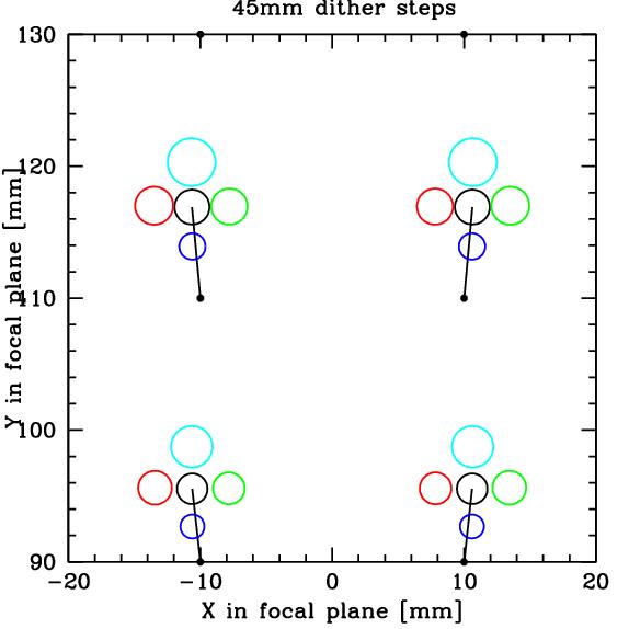
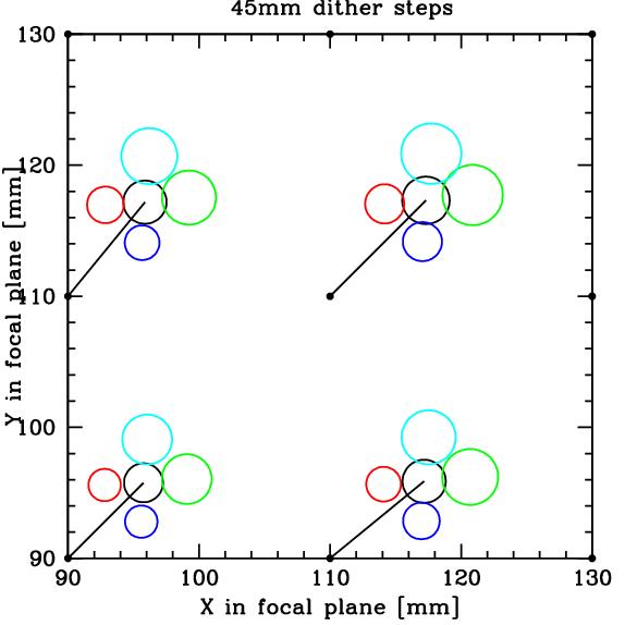
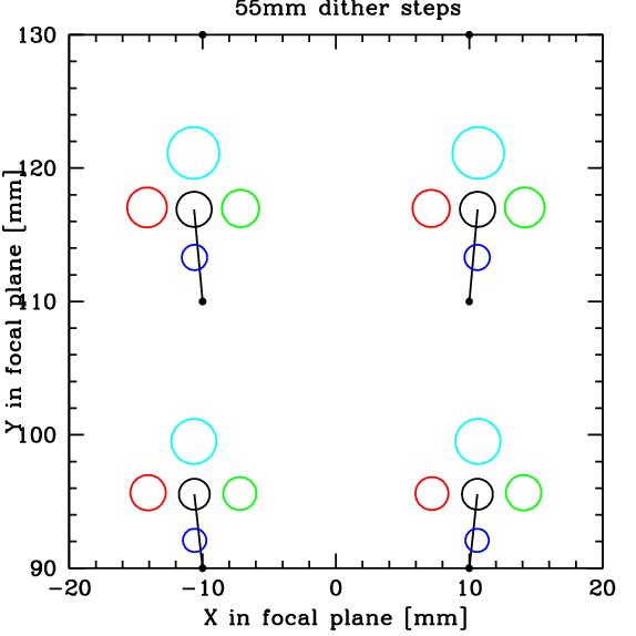
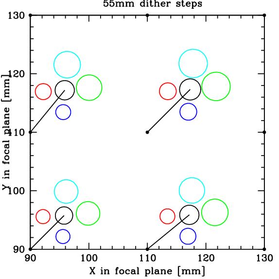
The locations of the ghosts in a 5-fold dithering pattern (offsets of
size STEP to the left, right, top and bottom) is illustrated in the
following figures. Each panel shows where the ghosts fall in each of 5
pointings near a grid of stars, at the center, side and corner of the
array. The black dot is primary image, and the different colours show
the locations of the ghost in the different dither positions. Click on
each image for full-size version.
| Step | Center of field | Top of field | Corner
of field |
5mm | 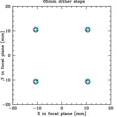 | 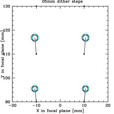 | 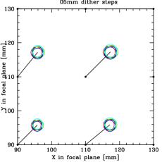 |
15mm | 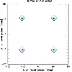 | 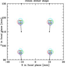 | 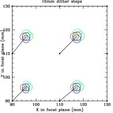 |
25mm | 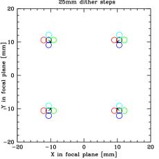 | 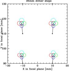 | 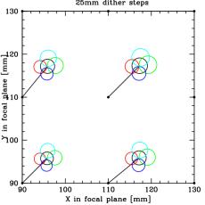 |
35mm | 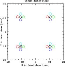 | 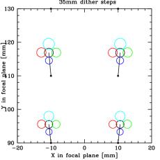 | 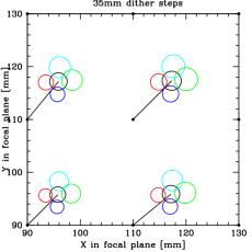 |
45mm | 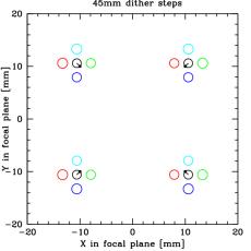 | 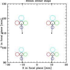 | 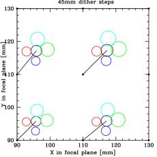 |
55mm | 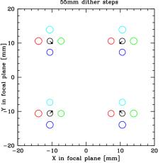 | 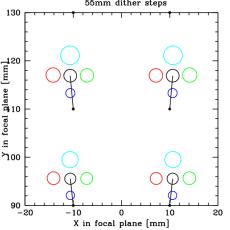 | 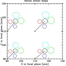 |
To avoid overlapping ghosts completely requires dither steps of +/- 55
mm, or nearly 1/4 of the field in either direction! With 25mm steps,
the ghosts do overlap in the corners (not in the center of the field),
but every part of the field avoids being under a ghost in at least two
exposure. These are still large offsets to take. It may be better to
ensure that ghost-affected pixels are flagged in the individual and
co-added images, but not actually masked out.